Add a power LED to a Weller WE1010 soldering station

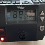
Some time ago I bought a Weller WE1010 soldering station. On all product photos it looks as if the display has a backlight - unfortunately this is not the case. Not even the on/off switch is illuminated, like on the old models. Shame on you Weller, that really goes better - especially for the price!

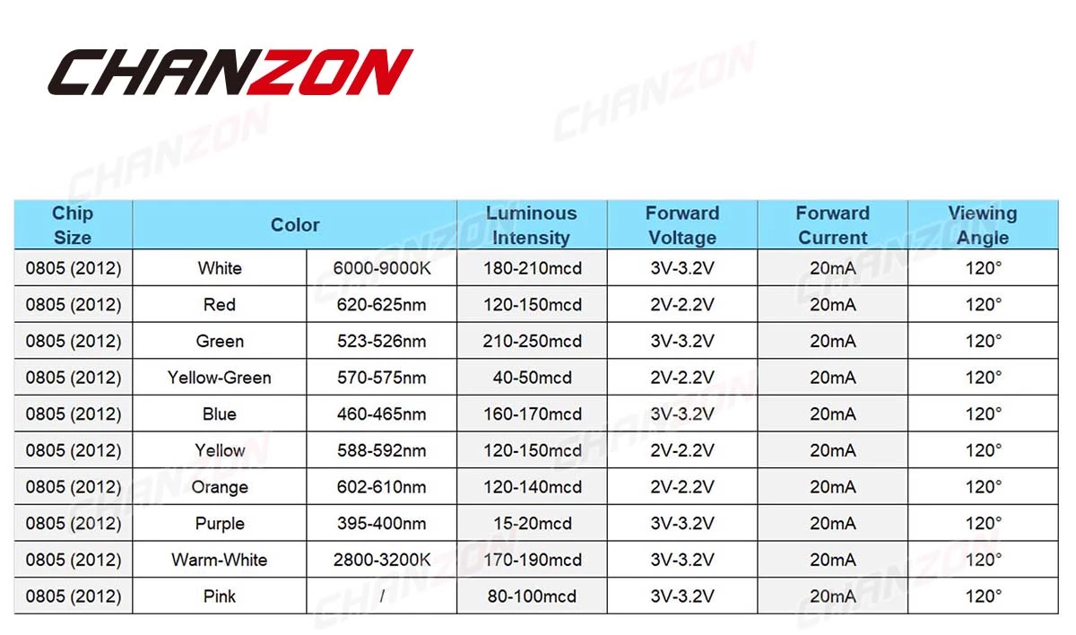
A backlight for the display would improve the readability enormously, but a retrofit is not so easy. I have instead installed a light under the on/off switch to see at least better whether the soldering station is switched on. I get the power directly from transformer, which supplies around 24V/AC. As LED i used this great Red 6mm 12-24V AC/DC LED.

Disclaimer

I assume no warranty or responsibility for any damage or injury. The conversion is at your own risk! When opening devices that are operated with mains voltage there is danger to life!

Parts

Assembly

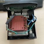
  1. Open soldering station by removing the two screws on the back
  2. At this point, the housing can be carefully lifted with a flat screwdriver
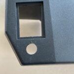
  3. Then I removed the on/off switch and drilled a 6mm hole 12mm below the opening for the LED. Since there is so much space, one could think that Weller wanted to install an LED here - who knows?
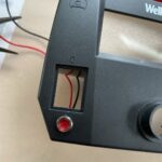
  4. Insert the LED
  5. Protect LED cables with some tube
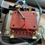
  6. Solder LED wires to the 24V output from the transformer
  7. Test and reassemble

Images

Video

Links

The links to AliExpress are advertising links. I would be happy if you use this link, but of course you don't have to. I have linked exactly the offers from which I have also bought and was satisfied with the supplier and the goods. The products can of course be bought anywhere.

C/C++/Arduino Datatypes

Type Byte Bit Typical Range
boolean 1 8 true/false
char 1 8 -128 to 127
signed char 1 8 -128 to 127
unsigned char 1 8 0 to 255
byte 1 8 0 to 255
uint8_t 1 8 0 to 255
int 2 16 -32,768 to 32,767
short 2 16 -32,768 to 32,767
signed int 2 16 -32,768 to 32,767
unsigned int 2 16 0 to 65,535
word 2 16 0 to 65,535
uint16_t 2 16 0 to 65,535
long 4 32 -2,147,483,648 to 2,147,483,647
float 4 32 3.4E +/- 38 (7 digits)
unsigned long 4 32 0 to 4,294,967,295
uint32_t 4 32 0 to 4,294,967,295
double 8 64 1.7E +/- 308 (15 digits)
uint64_t 8 64 0 to 18,446,744,073,709,551,615

Calculate series resistor for 0805 SMD LEDs with different colors

When I plan SMD LEDs for one of my PCB designs, I always ask myself which series resistors I need. At AliExpress dealer CHANZON Official Store I found the following nice overview. The series resistor can then be calculated with hte LED Resistor Calculator.

Can’t import SVG’s to Fritzing Part Editor created with Adobe Illustrator

When I tried Fritzing for the first time today, I unfortunately had to notice that two parts are missing. A NodeMCU has already created and released squix78, thanks for that. But unfortunately I could not find a RS232-TTL converter (MAX3232). No problem, then I just create an own part. With this manual this is relatively easy. Unfortunately the part editor did not accept the SVG's I created with Adobe Illustrator. After a long time of trying I found out that the following export settings are necessary. Important is the number of decimal places:

The final part:

You could download my MAX3232 RS232-to-TTL-Converter Breakout Board here. To use it, drag and drop it into you sketch.


Download Fritzing for free (with out donation)

I just wanted to test Fritzing today, but it is not so easy to download the program. On the website it is only possible to download it after a PayPal donation. Unfortunately the binaries are not available on github. Please don't get me wrong, I don't have anything against donating for free software, but I don't like to force this on everyone. At the end, I found something after all:

TL;DR: Sign up for an acccount (or use bugmenot.com) and then you can select "I already paid" and download the binary for you platform. If you like Fritzing, please donate.

FDTI USB-to-Serial adapter showing only gibberish

I order two new - cheap - FTDI FT232RL USB-to-Serial Adapters on AliExpress.

IMG_7764

After connecting, the first disappointment came directly. The Windows Device Manager displayed no COM port. Only a USB Serial Converter. The update of the driver brought no improvement. By coincidence I discovered the "Load VCP" option. After I activated this, the USB Serial Interface was displayed correctly.

2016-09-04 16_49_23-Eigenschaften von USB Serial Converter

Quickly the next disappointment came, both showing only gibberish.

I thought at first that the baud rate is incorrect, but with an older adapter it working correctly. On the FTDI website i found a tool called "FT_Prog". With these programming utility you can read and write the EEPROM for use with FTDI devices. After a few clicks I could see the difference:

2016-09-04 16_24_14-FTDI - FT Prog - Device_ 0 [Loc ID_0x212]

2016-09-04 16_28_39-FTDI - FT Prog - Device_ 0 [Loc ID_0x212]

Since I was not sure if there are other differences, I used the template function of the tool to copy the settings.

2016-09-04 16_37_31-FTDI - FT Prog - Device_ 0 [Loc ID_0x212]

2016-09-04 16_38_10-FTDI - FT Prog - Device_ 0 [Loc ID_0x212]

2016-09-04 16_38_39-Program Devices